
What Is a LiFePO4 BMS? Functions, Parameters & Selection Guide (2026)

Table of Contents
- Introduction: What Is a BMS for a LiFePO4 Battery?
- Why LiFePO4 Batteries Need a Dedicated BMS
- How a LiFePO4 BMS Works
- Core Functions of a LiFePO4 BMS
- Protection Features Explained: OVP, UVP, OCP, SCP, OTP, UTP
- Key BMS Parameters & How to Read Them
- Active vs Passive Balancing in a BMS
- BMS Communication: CAN Bus, RS485/Modbus & Bluetooth
- How to Choose a BMS for LiFePO4: Step by Step
- Choosing a 48V (16S) BMS for Rack & ESS Systems
- BMS Settings & Charger/Inverter Matching
- B2B Buyer's Checklist: Questions for Your BMS Supplier
- BMS & Battery Certifications to Require
- Related Resources
- Frequently Asked Questions
- Summary
What Is a LiFePO4 BMS? Functions, Parameters & Selection Guide (2026)
Last updated: September 2026 | Written by the Enerbe Engineering Team
Introduction: What Is a BMS for a LiFePO4 Battery?
Quick Answer: A BMS (Battery Management System) is the electronic "brain" of a LiFePO4 battery. It measures every cell's voltage, the pack current and temperature, then opens and closes charge/discharge MOSFETs to keep the cells inside a safe window—typically 2.5V–3.65V per cell, 0–45°C charging. A LiFePO4 BMS provides over/under-voltage, over-current, short-circuit and temperature protection, balances the cells, estimates state of charge, and (on smart models) reports data over CAN bus, RS485/Modbus or Bluetooth. You cannot safely run a series LiFePO4 pack without one. Choosing the right BMS means matching the cell count (4S/8S/16S), continuous and peak current, balancing type and communication protocol to your load and inverter.
A LiFePO4 BMS is the single most important component determining the safety, usable capacity and service life of a lithium iron phosphate battery. The cells store the energy, but the battery management system decides when charging and discharging are allowed, protects the cells from abuse, and keeps all cells matched as the pack ages. For OEMs, system integrators, dealers and project buyers, understanding how a BMS for LiFePO4 batteries works—and how to read its parameters—is essential when comparing quotes and avoiding field failures.
This guide explains, in plain engineering terms, what a BMS does on a LiFePO4 battery, how it works, what every specification on a datasheet means, the difference between active and passive balancing and between a smart and a basic BMS, and how to choose and configure the correct BMS for 12V, 24V and 48V systems—including rack-mounted commercial ESS. It is a selection and reference guide, not a repair procedure.
Already have a battery that reads 0V or won't respond?
This article explains how a BMS is designed and selected; it does not cover recovery. If a BMS has already cut the pack out, follow our step-by-step How to Reset a BMS on a LiFePO4 Battery guide. If the pack is deeply discharged and sleeping, use the LiFePO4 battery wake-up / revive guide instead.
For a broader introduction to the chemistry itself, see our What Is a LiFePO4 Battery complete guide.
Why LiFePO4 Batteries Need a Dedicated BMS
LiFePO4 cells are forgiving compared with NMC—they are thermally stable and tolerate deep cycling—but they are not immune to damage from over-voltage, under-voltage, over-current or overheating. What makes a BMS non-negotiable is the way cells behave when connected in series.
A 12V pack is 4 cells in series (4S), a 24V pack is 8 cells (8S), and a 48V pack is 16 cells (16S). In series, every cell sees the same current, but no two cells are perfectly identical: small differences in capacity, internal resistance and self-discharge mean they charge and discharge at slightly different rates. Over hundreds of cycles these differences compound. The strongest cell reaches 3.65V first and forces charging to stop—leaving the others under-charged—while the weakest cell reaches 2.5V first and forces discharge to stop, even though the rest still hold energy. Without per-cell monitoring, one cell can be silently pushed past its limits cycle after cycle.
| Abuse condition | What happens to an unprotected LiFePO4 cell | BMS response |
|---|---|---|
| Over-charge (>3.65V) | Accelerated capacity fade, gas generation, swelling; severe cases risk venting | Charge MOSFET opens (OVP) |
| Over-discharge (<2.5V, especially <2.0V) | Copper dissolution, irreversible capacity loss, inability to recharge | Discharge MOSFET opens (UVP) |
| Over-current / short circuit | Overheated busbars and cells, damaged terminals, thermal risk | MOSFET disconnect in milliseconds (OCP/SCP) |
| Charging below 0°C | Lithium plating on the anode, permanent capacity loss and internal short risk | Charge path disabled (UTP) until warm |
| Cell imbalance | Reduced usable capacity, early cut-off, premature failure of the weakest cell | Cell balancing during charge |
A generic "lithium" BMS is not always suitable for LiFePO4. The charge and cut-off voltages differ from NMC and LCO, so a dedicated LiFePO4 BMS—with LiFePO4 voltage profiles and, ideally, a low-temperature charge inhibit—should always be specified. For the chemistry-level safety comparison behind these limits, see are LiFePO4 batteries safe?
How a LiFePO4 BMS Works
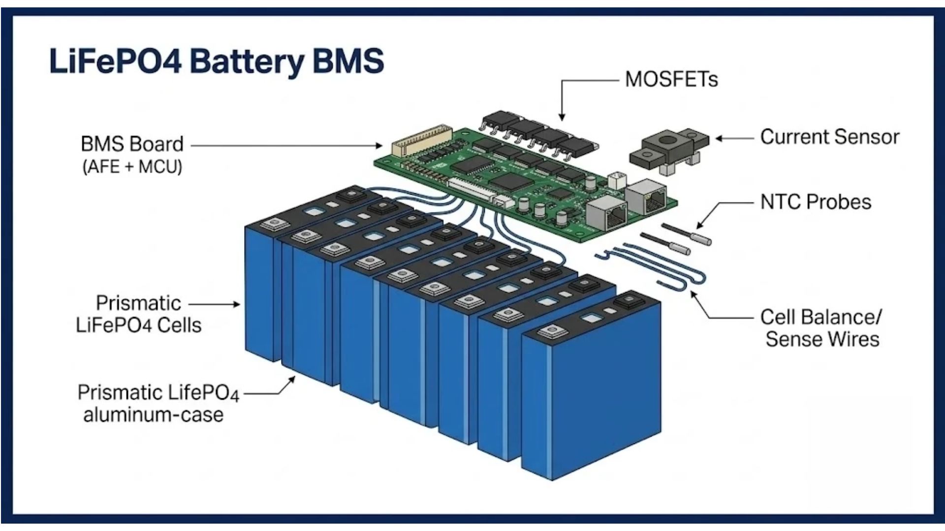
A modern LiFePO4 battery BMS is built around an analog front end (AFE) IC—such as the BQ769x, ADI/LTC or comparable family—that measures each cell voltage through a set of balance/sense wires, a microcontroller running the protection and balancing logic, banks of power MOSFETs on the charge and discharge paths, a current sensor (shunt or Hall-effect), and one or more NTC temperature probes.
The control loop, step by step
-
Measure: the AFE samples every cell voltage (typically every 100ms–1s, with ±1–5mV accuracy on good designs), pack current and temperature(s).
-
Estimate: the controller integrates current over time (coulomb counting) and combines it with voltage to estimate state of charge (SOC) and state of health (SOH).
-
Protect: if any parameter crosses a threshold, the BMS opens the charge MOSFET, the discharge MOSFET, or both, and latches a fault code.
-
Balance: near the top of charge, when cell-to-cell spread exceeds the balance threshold, the BMS bleeds the highest cells (passive) or transfers energy (active) until they converge.
-
Communicate: a smart BMS publishes per-cell voltage, current, SOC, temperatures, alarms and cycle count over CAN/RS485/Bluetooth so an inverter, SCADA or app can display and log them.
The charge and discharge paths use separate MOSFET banks, which is why a pack can sometimes accept charge but show no output (or vice versa) after a fault. The BMS draws a small standby current—quality designs keep this under ~20–30mA in operation and under ~1mA in deep sleep, which matters for batteries that sit in storage. For storage best practice see the LiFePO4 storage and maintenance guide.
Key Point: Protection is instantaneous and hardware-based; monitoring and balancing are continuous. A BMS that only reports pack voltage (not per-cell voltage) cannot detect a single failing cell. For B2B deployments, always require per-cell voltage reporting—you cannot manage what you cannot measure.
Core Functions of a LiFePO4 BMS
A full-function battery management system for LiFePO4 combines protection, balancing, estimation and communication. Cheaper "protection boards" implement only the first group; a genuine smart BMS adds the rest.
| Function group | What it does | Basic BMS | Smart BMS |
|---|---|---|---|
| Cell protection | OVP, UVP, OCP, SCP, OTP, UTP cut-offs | Yes | Yes |
| Cell balancing | Equalises cell voltage during charge | Passive (often) | Passive / active |
| SOC / SOH estimation | Coulomb counting + voltage, cycle logging | No / basic LEDs | Yes |
| Communication | CAN, RS485/Modbus, Bluetooth | No | Yes |
| Per-cell diagnostics | Reports each cell voltage, temps, fault history | No | Yes |
| Pre-charge / soft start | Limits inrush into inverter capacitors | Rare | Common on rack BMS |
| Firmware / configurability | Adjustable thresholds, field updates | No | Yes |
Protection Features Explained: OVP, UVP, OCP, SCP, OTP, UTP
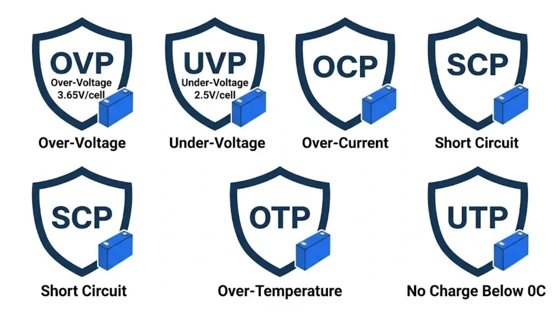
The figures below are typical industry values for LiFePO4; exact thresholds vary by cell manufacturer and BMS configuration and should always be confirmed against the cell datasheet.
| Protection | Trigger (per cell unless noted) | Recovery | Action |
|---|---|---|---|
| OVP – over-voltage (charge) | 3.65V | ~3.40–3.50V | Stops charging |
| UVP – under-voltage (discharge) | 2.50V (hard damage line ~2.0V) | Charging resumes >~2.80–3.00V | Stops discharge |
| OCP – over-current | Exceeds continuous rating; or peak rating for longer than its pulse window | Load removed / restart | Opens discharge path |
| SCP – short circuit | Very high current (often >2–3× peak) | Automatic after short removed (with delay) | Disconnect in <1–10ms |
| OTP – over-temperature | ~55°C charging / ~65°C discharging | Cool to ~50°C | Pauses charge/discharge |
| UTP – low-temperature charge | <0°C charging (discharge usually allowed to ~−20°C) | >~3–5°C | Blocks charge only |
Note the asymmetry of the temperature rule: LiFePO4 can generally discharge at sub-zero temperatures but must not be charged below 0°C, because charging plates lithium metal onto the anode. Batteries for cold climates should specify a self-heating function controlled by the BMS. For thermal safety and venting behaviour see the LiFePO4 battery safety guide.
Key BMS Parameters & How to Read Them
When comparing a LiFePO4 battery BMS datasheet, these are the parameters that determine whether it fits an application. Matching them correctly is the core of BMS selection.
| Parameter | Meaning | Typical / guidance |
|---|---|---|
| Cell count (S) | Number of series cells; sets nominal voltage | 4S=12.8V, 8S=25.6V, 16S=51.2V |
| Continuous discharge current | Current the MOSFETs carry indefinitely without overheating | Must exceed max steady load with 20–25% headroom |
| Peak / pulse current | Maximum current and the seconds it is sustained | Must cover inverter surge (often ~2× for 5–30s) |
| Charge current | Maximum allowed charge from charger/MPPT | Commonly 0.2C–0.5C of capacity |
| Voltage sampling accuracy | Precision of per-cell measurement | ±5mV or better; ±10mV is weak |
| Balance current / type | Current used to equalise cells | Passive 50–100mA; active 1–10A |
| Balance threshold | Cell spread that starts balancing | 20–50mV; target spread <10–20mV |
| Temperature sensors | Number and placement of NTC probes | At least 2–3; one near cells, one near MOSFETs |
| Standby / sleep current | BMS self-consumption | <20–30mA active, <1mA sleep |
| Communication | Data interface(s) and protocols | CAN / RS485-Modbus / Bluetooth / LCD |
A common shortcut is to size the BMS by battery capacity alone (e.g. "100Ah pack → 100A BMS"). This is a useful rule of thumb—a 1C-rated BMS matches a 100Ah pack—but the load is what really sets the requirement. A 100Ah 48V battery feeding a 5kW inverter pulls roughly 100A continuously before efficiency losses, while the same battery running a 1kW load needs far less. Always size from the load's continuous and surge current, then verify the pack can deliver it.
Active vs Passive Balancing in a BMS

Balancing keeps series cells at the same state of charge. There are two approaches, and the choice belongs in your BMS selection criteria.
| Attribute | Passive balancing BMS | Active balancing BMS |
|---|---|---|
| Method | Bleeds high cells through resistors as heat | Transfers energy between cells via DC-DC |
| Balance current | 50–100mA | 1–10A |
| Cost / complexity | Low, simple, reliable | Higher, more components |
| Best fit | Most packs <50kWh, RV/marine/golf/small ESS | Large/high-voltage ESS where every Wh counts |
For the majority of commercial batteries under ~50kWh, a well-designed passive BMS is sufficient and cost-effective; the energy lost as heat is negligible. Active balancing pays back in very large packs where balancing time and efficiency matter. Crucially, BMS quality matters more than the balancing label—a reputable passive BMS that reports per-cell voltage outperforms a poorly built "active" unit. The full mechanics, thresholds and timing are covered in our dedicated how to balance LiFePO4 batteries guide.
BMS Communication: CAN Bus, RS485/Modbus & Bluetooth
Communication is what separates a smart LiFePO4 BMS from a basic protection board, and it is frequently the source of integration problems when batteries are paired with third-party inverters.
| Interface | Typical protocol | Best used for |
|---|---|---|
| CAN bus | CANopen / J1939; Pylontech-, Solis-, GoodWe-, Deye-compatible profiles | Inverter/PCS integration in ESS, automotive, multi-module racks |
| RS485 | Modbus RTU (sometimes proprietary) | Industrial SCADA/BMS monitoring, long cable runs, telemetry |
| Bluetooth | Manufacturer app | Local commissioning, per-cell diagnostics, firmware |
| LCD / LED | Local display | Front-panel SOC, voltage, alarms on rack modules |
B2B Buying Tip: A physical CAN/RS485 port is not enough—the protocol profile must match your inverter. Ask for the battery's inverter compatibility list and the exact protocol (e.g. "Pylontech CAN profile" or a Modbus register map). Without a matching profile the inverter will not read SOC or may refuse to charge. For rack deployments, require per-cell and per-module reporting and a documented register map.
How to Choose a BMS for LiFePO4: Step by Step
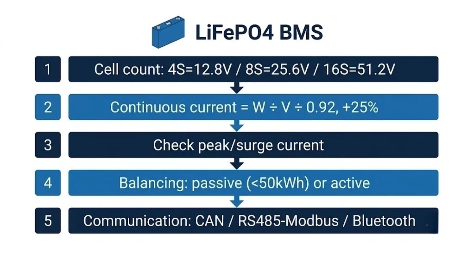
Follow this sequence to choose a BMS for LiFePO4 cells without under-rating (nuisance trips) or over-paying for capacity you don't need.
-
Fix the cell count / voltage. Count your series cells: 4S for 12.8V, 8S for 25.6V, 16S for 51.2V. The BMS must match exactly—a 16S BMS cannot run a 14S or 15S pack.
-
Calculate maximum continuous load current. I(A) = inverter/load power(W) ÷ battery voltage(V) ÷ efficiency (~0.9–0.95). Example: 5000W ÷ 51.2V ÷ 0.92 ≈ 106A, so specify a BMS with at least ~125–135A continuous (20–25% headroom).
-
Check peak/surge current and duration. Inverters draw roughly 2× rated for several seconds on motor and capacitor startup. The BMS peak rating and its pulse window (e.g. 200A for 10s) must cover it.
-
Match charge current. Ensure the BMS charge rating covers your charger and solar MPPT combined current.
-
Choose balancing. Passive for packs <50kWh; active for large/high-voltage ESS or tightly matched capacity requirements.
-
Specify communication. Pick the protocol your inverter/SCADA requires (CAN profile or RS485 Modbus); add Bluetooth for commissioning.
-
Apply environmental rules. Add low-temperature charge inhibit (and self-heating for cold climates) and adequate NTC coverage.
-
Require diagnostics and updates. Per-cell voltage reporting, fault/event logging and field-upgradable firmware.
For the battery itself—capacity, runtime and supplier qualification—use the how to choose a LiFePO4 battery supplier guide and the BESS supplier selection criteria.
Choosing a 48V (16S) BMS for Rack & ESS Systems
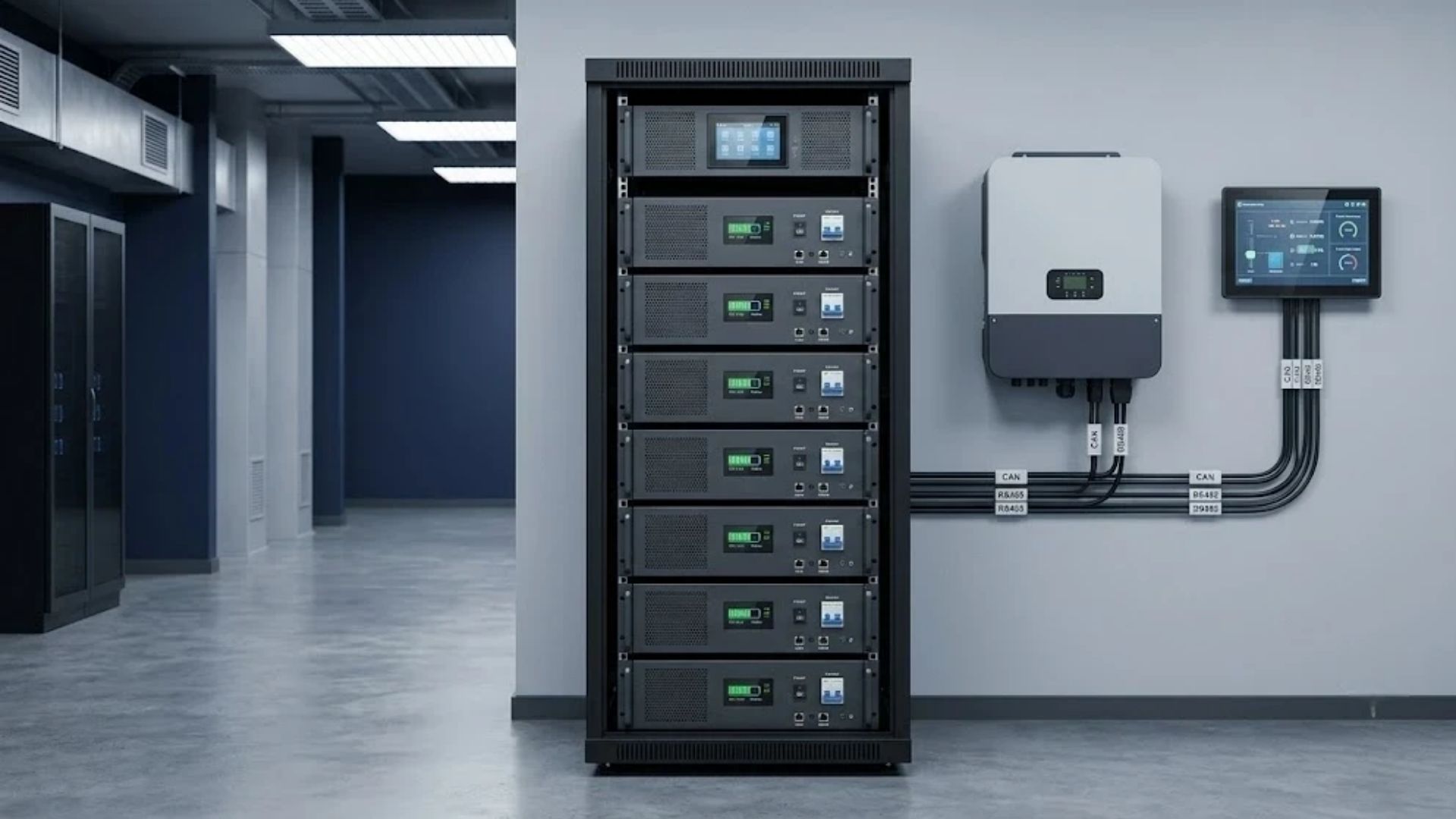
Searches for a "LiFePO4 BMS 48V" usually mean a 16S management system for a 51.2V nominal pack. Rack-mounted commercial ESS adds requirements that small drop-in batteries do not have:
-
Hierarchical architecture: a master BMS (battery management unit) coordinates module-level slave boards, each protecting its own 16S group and reporting to the rack controller.
-
Parallel-module coordination: when modules or racks are paralleled, the BMS must support controlled pre-charge and current sharing so a full module cannot dump inrush current into an empty one.
-
Inverter-ready communication: CAN (often a Pylontech-compatible or vendor profile) and RS485/Modbus, with a published compatibility list and register map.
-
Front-panel control: status LEDs or LCD, a manual reset/control switch and clearly labelled fault indication per module.
-
High continuous current: rack packs commonly run 50–200A+, so MOSFET count, busbar rating and thermal design are decisive.
Note the correct LiFePO4 voltage for a 16S pack: nominal 51.2V, charge voltage 57.6–58.4V (3.60–3.65V per cell), low-voltage alarm around 48V and hard cut-off near 40V (2.5V per cell). A value of 54.6V belongs to a 13S NMC pack, not LiFePO4—using it undercharges a LiFePO4 rack. For rack selection and sizing see the 48V rack-mounted lithium battery guide for project buyers and the rack-mounted battery product range.
BMS Settings & Charger/Inverter Matching
A correctly selected BMS still fails in the field if the charger and inverter thresholds do not match the LiFePO4 profile. These are the standard settings to align across the BMS, charger/MPPT and inverter (always confirm against the cell datasheet).
| System | Nominal | Charge / absorb voltage | Low-voltage alarm | Hard cut-off (2.5V/cell) |
|---|---|---|---|---|
| 12V (4S) | 12.8V | 14.6V | ~12.0V | 10.0V |
| 24V (8S) | 25.6V | 29.2V | ~24.0V | 20.0V |
| 48V (16S) | 51.2V | 57.6–58.4V | ~48.0V | 40.0V |
-
Set the charger/MPPT to the LiFePO4 profile (no equalisation stage, float at or near the absorb voltage or disabled) so it does not hold a high voltage that fights the BMS.
-
Set the inverter low-voltage cut-off above the BMS UVP—e.g. 48V inverter alarm/cut-off on a 16S pack—so the inverter shuts down gracefully before the BMS hard-disconnects.
-
Disable charging below 0°C at both the charger and BMS; use self-heating packs in cold sites.
-
Limit charge and discharge current in the inverter to within the BMS and cell ratings.
Full charge-voltage, current and stage-by-stage procedure is in the how to charge LiFePO4 batteries guide; commercial and industrial settings are covered in the C&I charging best-practice guide, and wiring/installation in the LiFePO4 installation guide. If a battery refuses to charge despite correct settings, work through the LiFePO4 not-charging troubleshooting guide.
B2B Buyer's Checklist: Questions for Your BMS Supplier
When sourcing batteries or BMS for a project, ask these in writing and require datasheet evidence:
-
Cell count and exact voltage profile (charge, balance-start, alarm, cut-off) for the pack being quoted.
-
Continuous and peak current, with the peak duration in seconds—and whether ratings are measured at a stated ambient temperature.
-
Balancing type and current, balance threshold, and target cell spread.
-
Per-cell voltage reporting over the communication interface, plus sampling accuracy.
-
Communication protocols and inverter compatibility list; request the Modbus register map or CAN profile document.
-
Number and placement of NTC sensors, low-temperature charge inhibit and optional self-heating.
-
Standby and sleep current to avoid self-discharge during storage.
-
Pre-charge / soft-start for inverter capacitor inrush on rack systems.
-
Fault/event logging and field firmware updates (a "black box" greatly speeds warranty diagnosis).
-
Whether thresholds are configurable for your application and who sets them.
-
Certifications and warranty terms, including BMS-related failure coverage.
BMS & Battery Certifications to Require
A BMS is part of a certified battery system; it cannot be certified meaningfully in isolation. For stationary and mobile LiFePO4 products, project specs commonly require UN38.3 (transport), IEC 62619 and UL 1973 (battery/BMS safety for stationary and industrial applications), CE/EMC, and—at system level—UL 9540 / UL 9540A and NFPA 855 compliance for installed ESS. China-market and some export projects reference GB/T 36276 and the GB 38031 series. Always request the actual certificates and datasheets rather than a generic "CE/RoHS" claim.
-
Certification body requirements, UL 9540A thermal-runaway testing and NFPA 855 siting: BESS certification guide.
-
Engineering-level thermal-runaway and fire-protection detail: LiFePO4 thermal-runaway & BESS fire-protection engineering guide.
-
China GB 38031 requirements: GB 38031 battery safety standard guide.
Related Resources
-
How to Reset a BMS on a LiFePO4 Battery — step-by-step recovery when a BMS has cut the pack out, brand procedures and fault codes
-
How to Wake Up a LiFePO4 Battery — reviving a deeply discharged, sleeping/0V pack
-
How to Balance LiFePO4 Batteries — passive vs active balancing, thresholds and timing in depth
-
How to Charge LiFePO4 Batteries — correct voltage, current and charge stages
-
LiFePO4 Battery Not Charging? — troubleshooting the seven most common causes
-
48V Rack-Mounted LiFePO4 Battery Guide — rack sizing, architecture and procurement
-
What Is a LiFePO4 Battery? — chemistry, voltage, capacity and applications
-
BESS Certification Guide — UL 1973, IEC 62619, UL 9540A, NFPA 855 and more
Frequently Asked Questions
What is a BMS on a LiFePO4 battery?
A BMS, or Battery Management System, is the electronic controller built into a LiFePO4 battery that measures each cell's voltage, pack current and temperature; opens and closes the charge/discharge MOSFETs to keep cells within 2.5V–3.65V and safe temperatures; balances the cells; estimates state of charge; and—on smart models—reports data over CAN, RS485/Modbus or Bluetooth. It is the component that protects the cells from over-charge, over-discharge, over-current, short circuit and temperature abuse.
Do LiFePO4 batteries need a BMS? Can I run them without one?
Yes, every series-connected LiFePO4 pack needs a BMS. Individual cells in a series pack have small capacity and resistance differences, and without per-cell protection the strongest cell can be overcharged and the weakest over-discharged on every cycle, causing rapid capacity loss, swelling or failure—with no over-current or short-circuit protection. A small single-cell project may run without one, but any multi-cell 12V/24V/48V battery must have a correctly rated LiFePO4 BMS.
How does a LiFePO4 BMS work?
An analog front-end chip continuously measures every cell voltage, current and temperature and feeds it to a microcontroller. The controller compares the readings against programmed thresholds; if any are exceeded it opens the charge or discharge MOSFET to disconnect the pack, near full charge it triggers cell balancing, and it integrates current to estimate SOC. On a smart BMS this data is published over CAN, RS485/Modbus or Bluetooth. Protection acts in milliseconds, while monitoring and balancing run continuously.
What size BMS do I need for my LiFePO4 battery?
Size the BMS from your load, not just the battery amp-hour rating. Calculate maximum continuous current as load watts ÷ battery voltage ÷ efficiency (~0.92), then add 20–25% headroom; separately confirm the BMS peak rating covers the inverter's startup surge (often about 2× for several seconds). The cell count must match exactly (4S/8S/16S). As a rule of thumb a 100Ah pack often pairs with a 100A (1C) BMS, but a 5kW 48V inverter needs roughly a 125A continuous BMS regardless of capacity.
What is the difference between 4S, 8S and 16S BMS?
The number is the count of series cells the BMS manages, which sets the pack voltage: 4S = 12.8V nominal (14.6V charge), 8S = 25.6V (29.2V charge), and 16S = 51.2V (57.6–58.4V charge). A BMS is matched to one cell count—it has that many cell-sense channels—so a 16S BMS cannot be used on a 4S or 8S pack. Parallel strings do not change the required S count.
What is the difference between a smart BMS and a basic BMS?
A basic (or "dumb") BMS provides hardware protection and sometimes passive balancing, with no data output. A smart BMS adds a microcontroller with SOC/SOH estimation, per-cell voltage and temperature reporting, fault logging, configurable settings, firmware updates and communication over CAN, RS485/Modbus or Bluetooth. For fleets, rack ESS and any inverter-integrated system, a smart BMS is effectively mandatory; basic boards suit simple, non-networked drop-in batteries.
Active vs passive BMS balancing—which do I need?
Passive balancing (50–100mA, bleeding high cells as heat) is reliable, low-cost and sufficient for nearly all packs under about 50kWh—RV, marine, golf and small ESS. Active balancing (1–10A, transferring energy between cells) is faster and more efficient and pays off in large or high-voltage ESS where balancing time and every watt-hour matter. BMS build quality and per-cell reporting matter more than the active/passive label. See our balancing guide for the detail.
What are the correct charge and cut-off voltage settings for a LiFePO4 BMS?
Per cell, charge to 3.65V and never discharge below 2.5V (2.0V is the permanent-damage line). By system: 12V/4S charges to 14.6V with a ~10.0V hard cut-off; 24V/8S to 29.2V with ~20.0V cut-off; 48V/16S to 57.6–58.4V with ~40.0V cut-off. Set inverter low-voltage alarms slightly above the BMS cut-off (e.g. ~48V on a 48V pack) so the inverter shuts down first. Note that 54.6V is a 13S NMC value, not LiFePO4.
Does a BMS drain the battery?
A BMS draws a small operating current. Quality designs stay under about 20–30mA while active and drop below ~1mA in sleep mode, which is negligible in normal use but can slowly flatten a pack over many months in storage—another reason to store LiFePO4 at 50–60% SOC and top up every 3–6 months. An unusually high self-discharge rate (a pack dropping quickly with no load) can instead indicate a BMS fault or internal short and should be investigated.
Why does the BMS stop charging below 0°C?
Charging LiFePO4 below 0°C causes lithium plating—metallic lithium deposits on the anode that permanently reduce capacity and can create an internal short. The BMS low-temperature charge protection (UTP) blocks only charging at low temperature; discharging is generally still permitted down to about −20°C. Charging automatically resumes once cells warm above roughly 3–5°C. Cold-climate installations should specify a BMS-controlled self-heating battery.
Is a 48V LiFePO4 BMS always 16S, and what communication do rack systems use?
A standard 48V LiFePO4 pack is 16S (51.2V nominal), so its BMS is a 16S unit. Rack and commercial ESS usually use a master BMS plus module-level slave boards, communicating with the inverter/PCS over CAN bus (often a Pylontech-compatible or vendor-specific profile) and with monitoring systems over RS485/Modbus, plus Bluetooth for local commissioning and an LCD/LED per module. Always confirm the protocol matches your inverter before ordering.
Can a BMS be replaced, and how long does it last?
The BMS is electronics rather than an electrochemically wearing part, so a well-made BMS usually lasts the life of the pack (the LiFePO4 cells, at 4,000–6,000+ cycles, typically age first). In modular or serviceable batteries the BMS board can be replaced, but it must be the correct S-count, current rating and firmware/configuration for the pack; an incorrectly specified replacement BMS is unsafe. Failed MOSFETs, current sensors or controllers should be serviced by the manufacturer, not bypassed—never run a pack with the BMS jumpered out.
Summary
The BMS is the safety and performance core of every LiFePO4 battery.
-
What it is: an AFE + microcontroller + charge/discharge MOSFETs that monitor every cell, current and temperature, protect the pack, balance cells, estimate SOC and communicate data.
-
Why it is mandatory: series cells drift apart; without per-cell protection the strongest cell overcharges and the weakest over-discharges, destroying capacity and creating safety risks.
-
Key limits: 2.5V–3.65V per cell; 4S/8S/16S = 12.8/25.6/51.2V; charge 14.6/29.2/57.6–58.4V; no charging below 0°C.
-
How to choose: match exact S-count, size continuous current to the load with 20–25% headroom, verify peak/surge rating, pick passive (<50kWh) or active balancing, and specify the CAN/RS485 protocol your inverter needs.
-
B2B essentials: require per-cell voltage reporting, ±5mV accuracy, NTC coverage, fault logging, upgradable firmware and real certificates (UL 1973 / IEC 62619 / UN38.3 / UL 9540A as applicable).
Enerbe manufactures LiFePO4 batteries with full-function smart BMS—per-cell monitoring, automatic passive balancing, low-temperature charge protection, CAN/RS485/Bluetooth communication and field-upgradable firmware—across 12V, 24V and 48V rack-mounted platforms for solar, telecom, data-center and commercial ESS projects. For datasheets, BMS parameter sheets, inverter compatibility lists or custom configurations, contact our engineering team or browse the LiFePO4 product range.
Get In Touch
Need BMS parameter sheets, protocol documents or a quote for smart-BMS LiFePO4 batteries? Contact Enerbe today.
📄 Request BMS Datasheet & Protocol Docs
Contact Us →📞 Speak with Our Engineering Team
Get In Touch →🔗 Browse Smart-BMS LiFePO4 Batteries
View Products →Dongguan A&S Power Technology Co., Limited.
Building 1, No. 2, Keji 9th Road,
Songshan Lake, Dongguan, Guangdong, China
📞 +86 137 1383 1631
✉ info@aspowerbattery.com
Stay Charged. Stay Connected.



How to Choose a LiFePO4 Battery Supplier: Company Types, Sourcing Path & B2B Checklist (2026)
Are LiFePO4 Batteries Safe? Fire, Explosion & Home Use Facts (2026)
Related Article


Get In Touch
Have questions about custom lithium batteries, energy storage solutions, or lead-to-lithium conversion? Our team is ready to help. Send us a message and we’ll respond within 24 hours.

Building 1, No. 2, Keji 9th Road, Songshan Lake, Dongguan, Guangdong, China
Office Address

info@aspowerbattery.com
Email Us

+86 137 1383 1631
Call Us

Sun - Fri (08AM - 10PM)
Office Open
