
LiFePO4 Thermal Runaway & BESS Fire Protection: Engineering Guide (2026)

Table of Contents
- Introduction: Why Thermal-Runaway Engineering Decides BESS Approvals
- What Is Thermal Runaway? (Quick Answer)
- The Electrochemical Stages of LiFePO4 Thermal Runaway
- LiFePO4 vs NMC/NCA: Onset Temperature & Heat-Release Data
- What Triggers Thermal Runaway: Mechanical, Electrical & Thermal Abuse
- Thermal Propagation: Cell to Module to Rack to Room
- How UL 9540A Testing Works (and How to Read the Report)
- How the BMS Prevents Thermal Runaway
- BESS Fire-Protection Engineering: Hierarchy of Controls
- Off-Gas, Toxic Gas & Deflagration Risk
- Codes at a Glance: NFPA 855, IFC & UL 9540
- Integrator's Fire-Safety Design & Procurement Checklist
- Frequently Asked Questions
- Related Resources
- Summary
LiFePO4 Thermal Runaway & BESS Fire Protection: Engineering Guide (2026)
Last updated: September 2026 | Written by the Enerbe Engineering Team
Introduction: Why Thermal-Runaway Engineering Decides BESS Approvals
Quick Answer: Thermal runaway is a self-reinforcing overheat event in which a cell's own exothermic reactions generate heat faster than it can escape. LiFePO4 (LFP) resists it far better than NMC/NCA—onset is around 270°C versus roughly 150–200°C, the phosphate cathode releases little oxygen, and propagation between cells is much slower. But "resists" is not "immune." For a commercial BESS, safety is an engineering result: Grade-A cells plus a protective BMS prevent most initiating faults, while cell spacing, fire barriers, thermal management, off-gas detection, deflagration venting and suppression contain the rare event. UL 9540A is the test that proves propagation control, and NFPA 855 / IFC are the codes that translate that test into a permitted, insurable installation.
For a system integrator, EPC contractor, project developer or fire marshal (AHJ), the question is rarely "is LiFePO4 safe?" at the chemistry level—that buyer-facing question is answered in our Are LiFePO4 Batteries Safe guide. The engineering question is harder: under exactly what conditions does a cell enter thermal runaway, how does that failure travel through a module, rack and battery room, and which design controls stop it before it becomes a loss?
This guide is the engineering companion to our general LiFePO4 battery safety guide. It covers the electrochemical stages of thermal runaway, trigger thresholds, thermal propagation, the four levels of UL 9540A, BMS protection logic, and the hierarchy of BESS fire-protection controls—including thermal management, fire barriers, off-gas and flammable-gas detection, deflagration venting, suppression and the spacing logic behind NFPA 855. For the certification paperwork and how to verify a supplier's documents, see the BESS certification & conformity guide.
What Is Thermal Runaway? (Quick Answer)
Thermal runaway is an uncontrolled positive-feedback loop inside a cell. Once the cell passes a critical temperature, exothermic (heat-releasing) reactions begin. The heat they produce raises the temperature further, which accelerates the reactions, which releases still more heat—faster than the enclosure can dissipate it. The cell vents hot gas, can ignite, and in the worst case propagates the failure to neighbouring cells.
Three things distinguish a manageable fault from a runaway event:
-
Heat-generation rate vs heat-removal rate. Runaway begins only when internal heat generation exceeds the pack's ability to shed heat to ambient. Cooling design matters as much as chemistry.
-
Oxygen availability. A decomposing cathode supplies oxygen internally, so a lithium fire does not need air. LFP's stable phosphate bond releases far less oxygen than NMC/NCA, which is the single biggest reason it behaves more gently.
-
Propagation, not the first cell, is what destroys a BESS. One cell venting is a contained incident; adjacent cells cascading is a total loss. Most system-level engineering targets propagation, not prevention of the statistically inevitable single-cell defect.
⚠️ Engineering Reality
A well-built LFP system is designed assuming one cell could fail, then proving—through UL 9540A large-scale testing—that the failure stops there. "Our chemistry never runs away" is not an acceptable safety case; "a single failure cannot propagate and the room handles the gas" is.
The Electrochemical Stages of LiFePO4 Thermal Runaway
Thermal runaway is not a single moment; it is a cascade of reactions that unlock one another as temperature climbs. Thresholds vary with state of charge (higher SOC = lower onset), cell format, ageing and abuse severity, so the figures below are typical engineering ranges, not fixed constants.
| Stage | Approx. Temperature | What Happens |
|---|---|---|
| 1. SEI decomposition | ~80–120°C | The protective solid-electrolyte-interphase film on the anode breaks down exothermically; the anode is then exposed to electrolyte. |
| 2. Anode–electrolyte reaction | ~120°C upward | The lithiated graphite reacts with electrolyte, releasing heat and combustible gases (H₂, CH₄, C₂H₄). |
| 3. Separator softening / meltdown | PE ~130°C / PP ~160°C | The polyolefin separator shrinks or melts, removing the barrier between anode and cathode and enabling a large internal short. |
| 4. Cathode decomposition & oxygen release | LFP ~270°C+; NMC ~200–250°C | The cathode breaks down and releases oxygen. LFP's strong P–O bond delays this and releases far less oxygen—the decisive safety advantage. |
| 5. Venting, ignition, possible propagation | Cell-dependent | Electrolyte vaporises, the safety vent opens and releases hot flammable/toxic gas; ignition and heating of adjacent cells may follow. |
The practical takeaway for design: LFP pushes stage 4—the oxygen-releasing, runaway-sustaining step—to a much higher temperature and produces a lower, slower heat pulse. That buys the thermal-management and propagation-control system precious minutes instead of seconds.
LiFePO4 vs NMC/NCA: Onset Temperature & Heat-Release Data
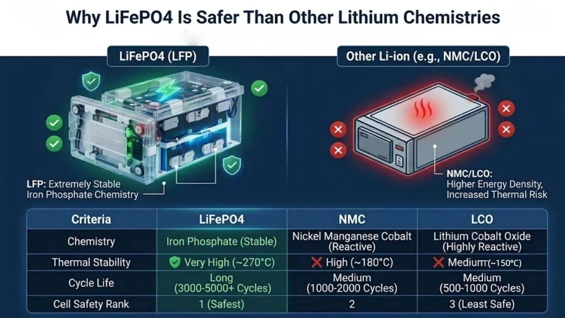
The cathode chemistry sets the ceiling. The table below summarises the characteristics that drive fire-protection design; exact values differ by specific cell formulation, SOC and test method (accelerating-rate calorimetry vs oven vs nail), so specify the supplier's tested data for your exact cell rather than relying on generic ranges.
| Parameter | LiFePO4 (LFP) | NMC (esp. 811) | NCA / LCO |
|---|---|---|---|
| Thermal-runaway onset | ~270°C+ ✅ | ~150–210°C | ~150–200°C |
| Oxygen released on decomposition | Low ✅ | High | Very high |
| Heat released / self-heating rate | Lower, slower ✅ | Higher, faster | Highest |
| Propagation tendency | Low–moderate ✅ | High | Very high |
| Nail-penetration behaviour | Often smokes/vents, no flame ✅ | Frequently ignites within seconds | Violent ignition common |
| Engineering consequence | Wider spacing/barrier margin; passive containment often achievable | Needs aggressive barriers, cooling, venting | Generally unsuitable for dense stationary ESS |
This is why LFP dominates stationary storage despite lower energy density: the safety margin at the cell level makes system-level propagation control realistic and economical. Energy density (90–120 Wh/kg for LFP vs 150–260 Wh/kg for NMC/NCA) matters in vehicles and phones; in a fixed battery room, safety, cycle life (4,000–6,000+ LFP cycles) and cost win—see our LiFePO4 lifespan data.
What Triggers Thermal Runaway: Mechanical, Electrical & Thermal Abuse
LFP cells do not enter runaway under normal use. Field failures trace back to one of three abuse families—or to an internal manufacturing defect that creates an internal short. The BMS is designed to block the electrical and thermal paths; it cannot always compensate for a crushed cell or a latent contamination defect, which is why cell quality and physical protection matter.
| Abuse family | Specific causes | Primary control |
|---|---|---|
| Mechanical | Crush, puncture/penetration, impact, seismic or vibration fatigue, swelling-induced pressure, dropped module during handling | Rigid enclosure, cell spacing/swell allowance, transport protection, qualified installation |
| Electrical | Overcharge beyond ~3.65 V/cell, deep discharge below ~2.5 V, external short, internal short (dendrite, contamination, weld defect), charging below 0°C causing lithium plating | BMS OVP/UVP/over-current, correct charger, low-temp charge lockout, Grade-A cells |
| Thermal | External fire, sustained high ambient, cooling-system failure, heat from high C-rate operation, resistive heating at loose/corroded terminals (arcing) | Thermal management with redundancy, torque-controlled terminations, derating, temperature monitoring |
Two triggers are routinely under-weighted in low-cost installations. The first is charging below 0°C, which plates lithium onto the anode; the plating can later pierce the separator and cause a delayed internal short weeks after the event. The second is poor DC connections—an under-torqued or corroded busbar acts as a heater bolted directly to a cell. Both are addressed by correct commissioning; see our LiFePO4 installation guide and charging guide.
Thermal Propagation: Cell to Module to Rack to Room
Thermal propagation is the spread of thermal runaway from the initiating cell to others. It is the phenomenon UL 9540A exists to measure and the focus of most BESS fire engineering. Heat transfers by four routes—conduction through busbars and the cell casing, convection of hot gas, radiation from flames, and flaming ejection of electrolyte. Propagation becomes self-sustaining when neighbouring cells absorb enough heat to cross their own onset threshold before the event is contained.
The four propagation boundaries
-
Cell → cell (within a module): controlled by cell spacing, inter-cell barriers (mica sheets, aerogel, ceramic/fibreglass blankets), and the cell can/vent orientation that directs gas away from neighbours.
-
Cell → module / module → module: controlled by module enclosure materials, intumescent coatings, internal fire barriers and the thermal-management circuit's ability to keep adjacent modules cool.
-
Module → rack / cabinet: controlled by rack compartmentalisation, exhaust ducting that carries vent gas out rather than across neighbouring modules, and cabinet-level detection and suppression.
-
Rack → rack / room → building: controlled by array spacing, fire-rated walls/barriers, ceiling height, deflagration venting, gas detection and the building suppression system—the domain of NFPA 855 and the UL 9540A installation-level test.
Key Point: LFP's lower heat pulse and minimal oxygen release mean passive, non-propagating module designs are genuinely achievable with proper barriers and spacing—something that is difficult and expensive with NMC. But this must be demonstrated on the exact production configuration, not assumed from the chemistry. A supplier claim of "non-propagating" without a UL 9540A module/unit report for that specific rack is marketing, not engineering evidence.
How UL 9540A Testing Works (and How to Read the Report)
UL 9540A is not a pass/fail certificate in the simple sense—it is a test method for evaluating thermal-runaway fire propagation in battery energy storage systems, run at four increasing scales. The data it produces is what the AHJ uses to justify spacing, ventilation and suppression decisions under NFPA 855 and the IFC. Note the distinction: UL 9540 certifies the complete energy-storage system for safety, while UL 9540A is the underlying thermal-propagation test. The full standards landscape and verification procedure is covered in our BESS certification guide.
| UL 9540A level | Test specimen | What it establishes |
|---|---|---|
| 1. Cell level | Single cell | Whether the cell enters thermal runaway, onset temperature, heat-release rate and composition/quantity of vent gas. |
| 2. Module level | Production module | Whether runaway propagates between cells; validates inter-cell barriers and spacing. |
| 3. Unit level | Cabinet / rack unit | Flammable-gas concentrations, explosion risk inside the enclosure, fire spread and suppression effectiveness at the cabinet. |
| 4. Installation level | Representative room / array | Real-world spacing, wall/ceiling distances, ventilation, deflagration venting and suppression—the data that lets the AHJ reduce default code setbacks. |
What to demand from the report
-
Configuration match: the tested cell, module and rack must be the exact models, layout and cooling arrangement you are buying—a report on a different rack or a lower-energy cell is not transferable.
-
Module/unit propagation result: explicit evidence on whether runaway propagated and over what time interval.
-
Gas data: measured vent-gas composition, volume and release rate—required to size ventilation and deflagration venting.
-
Installation-level conclusions that justify your proposed spacing and suppression, with the testing laboratory and report number.
For projects in China or using Chinese-manufactured cells, the mandatory GB 38031-2025 standard imposes its own stringent thermal-runaway and propagation requirements and is worth comparing against UL 9540A during technical review.
How the BMS Prevents Thermal Runaway
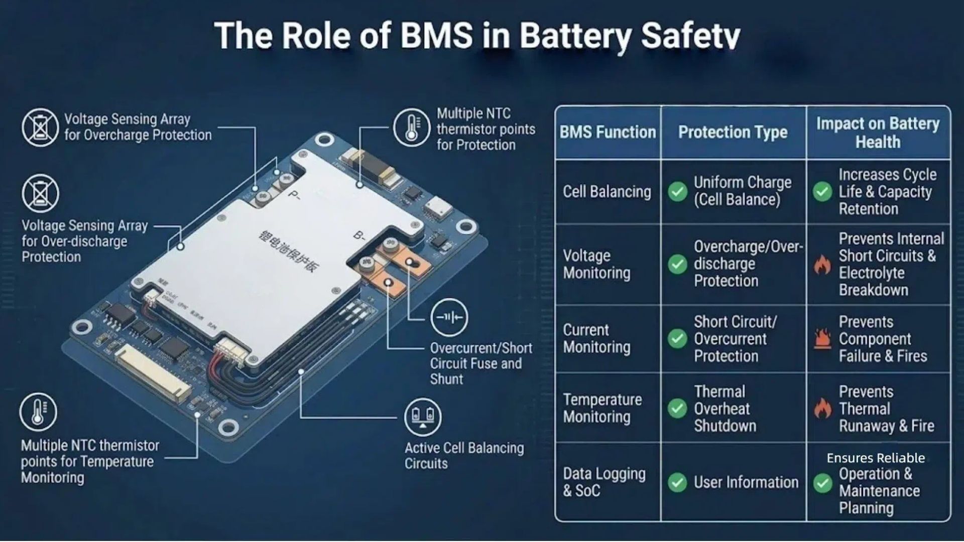
The Battery Management System is the first line of defence because it eliminates the electrical abuse paths before heat ever builds. A BMS suited to a commercial BESS monitors every cell and acts on thresholds well below runaway onset; it also provides the early-warning signals the room-level systems depend on.
| BMS function | Typical threshold (LFP) | Thermal-runaway link |
|---|---|---|
| Over-voltage protection | cuts charge at ~3.65 V/cell | Stops overcharge, lithium plating and electrolyte decomposition—a leading electrical trigger. |
| Under-voltage protection | cuts discharge at ~2.5 V/cell | Prevents copper dissolution and internal damage that can seed later shorts. |
| Over-temperature | alarm ~55–60°C, cut ~60–70°C | Opens contactors long before the ~270°C LFP onset; the single most direct interlock. |
| Low-temp charge lockout | inhibits charge below 0°C | Prevents lithium plating that causes delayed internal shorts. |
| Over-current / short circuit | fast disconnect (ms) | Limits I²R heating and external-short energy. |
| Cell balancing & per-cell monitoring | ±mV-class sensing | Prevents a weak cell being chronically overcharged; provides the earliest voltage/temperature anomaly warning. |
For integration, insist on a BMS that reports per-cell voltage and temperature over CAN/RS485, logs faults, and raises graded alarms (warning → derate → contactor open) that can be wired into the EMS and site fire alarm. Be clear-eyed about the limit: a BMS cannot stop a mechanically crushed cell or a latent internal manufacturing defect, which is exactly why propagation barriers and room-level controls remain necessary. BMS balancing logic is explained in our LiFePO4 cell-balancing guide.
BESS Fire-Protection Engineering: Hierarchy of Controls
Robust BESS fire safety is layered, following the classic safety hierarchy—remove the hazard, prevent initiation, contain propagation, detect early, manage gas, suppress, and separate. No single layer should be treated as sufficient.
1 – 2. Remove the hazard and prevent initiation
-
Specify LFP chemistry, Grade-A matched cells from a traceable manufacturer and a BMS with the full protection set above; audit the supplier's incoming-cell inspection and welding quality (see choosing a reliable BESS supplier).
-
Right-size cables and torque all DC connections to spec; enforce low-temp charge lockout and commissioning tests.
3. Thermal management: air vs liquid cooling
| Attribute | Air cooling | Liquid cooling |
|---|---|---|
| Heat removal / uniformity | Adequate; typical cell spread ~3–5°C | High; tighter spread (~2°C), handles hot spots |
| Best fit | Lower C-rate, smaller/de-rated, well-ventilated systems | High C-rate, dense racks, large utility/container ESS |
| Cost / complexity | Lower, simple, easy maintenance | Higher CAPEX, pumps/coolant and leak management |
| Failure mode to design for | Fan failure, blocked filters, uneven airflow | Coolant leak, pump failure; needs redundancy/alarm |
Whichever the method, design for the worst-case cell at maximum ambient and maximum C-rate, with fan/pump redundancy and a derating strategy on cooling fault. Rack format interacts with cooling—see our rack-mounted battery guide and the wall vs stackable vs rack comparison.
4. Contain propagation
-
Inter-cell and inter-module barriers: mica, aerogel, ceramic-fibre or intumescent pads, sized against the tested heat flux.
-
Reserve a swell/vent gap around prismatic cells and orient vents so gas exits the module, not into the next cell.
-
Compartmentalise racks and use fire-rated cabinet/container walls; confirm the assembly in the UL 9540A module/unit report.
5 – 6. Detect early and manage gas
Pre-ignition off-gas often appears seconds to minutes before smoke or flame, giving a detection window. Combine smoke/heat detection with combustible-gas detectors (hydrogen/CO, set against the LEL) at high level, and feed BMS temperature-rise alarms into the same panel. Detection triggers the exhaust/venting strategy before gas reaches an ignitable concentration (see next section).
7. Suppress and separate
-
Suppression: for stationary lithium ESS, large-flow water sprinkler systems are the most common code-accepted approach because they cool adjacent equipment and stop propagation, even if they do not extinguish the initiating cell instantly. Clean agents (e.g. FK-5-1-12/Novec-type) and aerosol systems can knock down flames but generally do not provide the same sustained cooling, so they are often paired with water cooling or justified by large-scale testing. The correct system is whatever the UL 9540A installation test and the AHJ accept for your configuration.
-
Separation: array-to-array, array-to-wall and array-to-property-line setbacks, fire-rated barriers and aisle widths limit spread and give fire-fighters access. Default values in NFPA 855 can often be reduced only when UL 9540A installation-level data supports it.
Off-Gas, Toxic Gas & Deflagration Risk
Before and during thermal runaway a cell vents a mixture whose exact composition depends on chemistry, SOC and temperature. For LFP this commonly includes hydrogen (H₂), carbon monoxide (CO), carbon dioxide (CO₂), methane (CH₄), ethylene (C₂H₄), vaporised carbonate electrolyte solvents, and—from fluorinated electrolyte salts/binders—trace hydrogen fluoride (HF) and phosphoryl fluoride (POF₃).
-
Deflagration (explosion) risk: H₂ and hydrocarbon gases are flammable over a wide range and can ignite if they accumulate between the lower and upper explosive limits in a poorly ventilated enclosure. This—not flame contact alone—is the main reason sealed indoor battery rooms need engineered exhaust and deflagration (pressure-relief) venting.
-
Toxicity/corrosion: CO is acutely toxic; HF is toxic and corrosive. Venting must protect both personnel and emergency responders.
-
LFP advantage: lower gas volume and release rate than NMC/NCA give more margin for detection and ventilation—but do not eliminate the requirement.
The UL 9540A unit-level test specifically measures gas volume, composition and release rate so the exhaust airflow rate and vent area can be engineered rather than guessed. Gas detection set-points, exhaust interlocks and explosion-relief panels should all trace back to that report.
Codes at a Glance: NFPA 855, IFC & UL 9540
The table is an orientation, not a substitute for the current editions—NFPA 855 and the International Fire Code (IFC) energy-storage provisions are revised periodically and the Authority Having Jurisdiction always has final say. Treat the numerical defaults as starting points that UL 9540A data can adjust.
| Document | Scope | Typical engineering concerns |
|---|---|---|
| NFPA 855 | US standard for stationary ESS fire safety | Location, size/energy limits, spacing/setbacks, separation from combustibles, detection, venting, suppression, signage, emergency response. |
| IFC (ESS chapter) | US model fire code adopted by many states | Similar indoor/outdoor energy thresholds, listings, separation and ventilation; often aligned with UL 9540A outcomes. |
| UL 9540 | Safety standard for the complete ESS | System listing (battery + inverter/controls); typically required alongside UL 1973 and UL 9540A. |
| UL 1973 / IEC 62619 | Battery/pack safety (US / international) | Cell and module safety baseline that underpin the system standards. |
Typical NFPA 855 design themes include conservative default energy limits for indoor systems (a low baseline kWh per room/area unless large-scale fire testing justifies more), outdoor grouping limits, default setbacks in the order of a few feet (roughly 0.9–1.5 m / 3–5 ft) depending on listing and test data, restrictions on certain locations (e.g. below-grade and certain occupied spaces), combustible-gas detection and ventilation, and automatic suppression. Always engineer to the edition adopted in your jurisdiction and confirm every deviation with the AHJ before installation. The full certification checklist is in our BESS certification guide.
Integrator's Fire-Safety Design & Procurement Checklist
Use this during supplier evaluation and detailed design; it complements the commercial due diligence in our BESS supplier selection criteria and system-integrator procurement guide.
-
UL 9540A reports at all relevant levels—cell, module, unit and, for room/container projects, installation—covering the exact production configuration you will install.
-
UL 9540 / UL 1973 / IEC 62619 listings verified against the issuing body's database, model-specific and current (see certification verification).
-
Cell traceability: Grade-A matched cells, manufacturer datasheet with onset-temperature / abuse-test data, ISO 9001 production and incoming inspection records.
-
BMS specification: per-cell voltage + temperature sensing, stated thresholds and response time, graded alarms, CAN/RS485 integration, fault logging and firmware updates.
-
Thermal management: max cell-to-cell temperature spread at worst-case ambient and C-rate, cooling redundancy, and derate-on-cooling-fault logic.
-
Propagation control: documented inter-cell/inter-module barrier materials and spacing, vent orientation, and the module/unit test proving non-propagation.
-
Detection & gas: smoke/heat plus combustible-gas (H₂/CO) detectors, detector placement, exhaust airflow and deflagration vent sizing derived from the UL 9540A gas data.
-
Suppression & layout: AHJ-approved suppression, array setbacks, fire-rated barriers, aisle access and signage, reconciled to NFPA 855/IFC and the installation-level test.
-
Commissioning & SAT: torque verification, insulation test, BMS alarm interlock test, detection/suppression functional test, and operator/responder training.
Frequently Asked Questions
At what temperature does a LiFePO4 battery enter thermal runaway?
The decisive cathode-decomposition step for LFP begins around 270°C+, versus roughly 150–200°C for NMC/NCA. Earlier reactions start lower—the SEI layer can begin decomposing around 80–120°C and the separator softens around 130–160°C—but LFP generally requires sustained external heating or severe abuse to reach self-sustaining runaway. Exact onset depends on SOC, cell format and test method, so use the cell manufacturer's calorimetry data for your specific cell.
Can thermal runaway propagate from one LiFePO4 cell to others?
Yes, it can—LFP resists propagation but is not immune. Heat from a venting cell can conduct through busbars and casings, and hot gas can heat neighbouring cells past onset. With proper inter-cell spacing, fire barriers (mica/aerogel), directed venting and thermal management, LFP modules commonly achieve non-propagation, but this must be demonstrated by a UL 9540A module/unit test on the exact production design rather than assumed from the chemistry.
What is UL 9540A and which test level do I need?
UL 9540A is the test method for evaluating thermal-runaway fire propagation in battery energy storage, run at four levels: cell, module, unit (cabinet/rack) and installation (room/array). At minimum a project needs cell and module data; cabinet products need unit-level results (including gas analysis); and indoor, room-based or container installations generally need installation-level testing to justify spacing, ventilation and suppression to the AHJ. UL 9540A is the test; UL 9540 is the system safety standard that uses such evidence.
What gases does a LiFePO4 battery release in thermal runaway?
Typical vent gases include hydrogen, carbon monoxide, carbon dioxide, methane, ethylene and vaporised carbonate electrolyte, with trace hydrogen fluoride (HF) and POF₃ from fluorinated salts. Hydrogen and hydrocarbons are flammable and can form an explosive mixture if they accumulate in a sealed enclosure; CO and HF are toxic. This is why BESS rooms need combustible-gas detection, forced exhaust and deflagration (pressure-relief) venting sized from UL 9540A gas measurements. LFP releases less gas more slowly than NMC, but the requirement still applies.
What fire suppression is best for a BESS?
For stationary lithium storage, large-flow water sprinkler systems are the most widely code-accepted because they continuously cool adjacent racks and stop propagation. Clean agents such as FK-5-1-12 and aerosol systems can suppress flames quickly but provide limited lasting cooling, so they are often combined with water cooling or validated by large-scale testing. The definitive answer for any project is the suppression method demonstrated effective in the UL 9540A installation-level test and accepted by the local AHJ under NFPA 855/IFC.
What spacing and ventilation does NFPA 855 require?
NFPA 855 sets default outdoor grouping/energy limits, indoor energy limits, and setbacks from walls, property lines and combustibles (commonly in the range of roughly 3–5 ft / 0.9–1.5 m depending on configuration and listing), plus aisle, detection, ventilation and suppression requirements. These defaults can often be reduced only when UL 9540A installation-level testing demonstrates safety. Because values vary by edition and jurisdiction, engineer to the adopted standard and confirm every deviation with the AHJ.
Does a good BMS make fire barriers and room suppression unnecessary?
No. The BMS prevents the electrical and thermal abuse paths (overcharge, over-discharge, over-current, over-temperature, sub-zero charging) and gives early warning, which stops the majority of potential initiations. It cannot prevent a mechanically crushed cell, an external fire, or a latent internal manufacturing defect. Defence-in-depth still requires cell-quality controls, propagation barriers, thermal-management redundancy, gas detection/venting and room-level suppression—each layer covers failures the others cannot.
Is liquid cooling or air cooling safer for a BESS?
Both can be safe when correctly designed. Air cooling is simpler and adequate for lower C-rate, smaller or well-ventilated systems; liquid cooling removes heat faster and holds a tighter cell-to-cell temperature spread, which suits high C-rate, dense, large utility/container deployments. The safety-relevant requirement is the same for both: keep every cell below its alarm threshold at worst-case ambient and load, with cooling redundancy and automatic derating or shutdown on cooling failure.
Related Resources
-
LiFePO4 Battery Safety Guide — buyer- and application-level safety overview, storage and emergency response
-
Are LiFePO4 Batteries Safe? — direct answers on fire/explosion risk, home and indoor use
-
BESS Certification & Conformity Guide — UL 1973, UL 9540/9540A, IEC 62619, EU 2023/1542 and certificate verification
-
GB 38031-2025 Standard Guide — China's mandatory thermal-runaway and propagation requirements
-
How to Choose a Reliable BESS Supplier — factory and quality-system due diligence
-
BESS Procurement Guide for Integrators — end-to-end commercial and technical sourcing
-
What Is a Battery Energy Storage System? — BESS components and architecture
-
How to Balance LiFePO4 Batteries — BMS cell balancing and per-cell monitoring
-
How to Install a LiFePO4 Battery — wiring, torque and commissioning practice
-
LiFePO4 Battery Shipping Certifications — UN38.3 transport safety
Summary
LiFePO4 thermal-runaway and BESS fire protection is an engineering system, not a single feature:
-
Chemistry buys margin: LFP onset (~270°C), low oxygen release and slow heat pulse make passive non-propagation realistic; NMC/NCA start far lower and burn harder.
-
Runaway is staged: SEI breakdown → anode reaction → separator meltdown → cathode oxygen release → venting/ignition; each stage is a potential interlock point.
-
Propagation is the real enemy: design across four boundaries (cell, module, rack, room) with spacing, barriers, vent direction and cooling.
-
UL 9540A proves it: demand cell/module/unit (and installation, where relevant) reports on the exact configuration, including gas data for venting design.
-
Layer the controls: Grade-A cells + full-protection BMS prevent initiation; thermal management, barriers, gas detection, deflagration venting, suppression and NFPA 855 separation contain the rare event.
-
The BMS cannot do it alone: it stops electrical/thermal abuse but not crush damage or latent defects, which is why defence-in-depth is non-negotiable.
Enerbe supplies LFP batteries and rack systems for BESS integrators with full-protection, per-cell-monitoring BMS, documented thermal-management and propagation design, and the UL/IEC/UN test documentation your AHJ and insurer expect. For the test reports, configuration data or a fire-safety engineering review of your project, contact our engineering team or browse certified LiFePO4 products.
Get In Touch
Need UL 9540A documentation or a fire-safety engineering review for your BESS project? Contact Enerbe today.
📄 Request UL 9540A Test Report & Datasheet
Contact Us →📞 Speak with Our Engineering Team
Get In Touch →🔗 Browse Certified LiFePO4 Products
View Products →Dongguan A&S Power Technology Co., Limited.
Building 1, No. 2, Keji 9th Road,
Songshan Lake, Dongguan, Guangdong, China
📞 +86 137 1383 1631
✉ info@aspowerbattery.com
Stay Charged. Stay Safe.



Are LiFePO4 Batteries Safe? Fire, Explosion & Home Use Facts (2026)
BESS Certification & Conformity Assessment Guide 2026: UL 1973, UL 9540, UL 9540A, IEC 62619 & GB 38031-2025
Related Article



Get In Touch
Have questions about custom lithium batteries, energy storage solutions, or lead-to-lithium conversion? Our team is ready to help. Send us a message and we’ll respond within 24 hours.

Building 1, No. 2, Keji 9th Road, Songshan Lake, Dongguan, Guangdong, China
Office Address

info@aspowerbattery.com
Email Us

+86 137 1383 1631
Call Us

Sun - Fri (08AM - 10PM)
Office Open
